Voltage in Parallel: Simple Guide That Will Save Your Life
Understanding voltage in parallel circuits is crucial for anyone working with electronics, as it directly impacts how devices function within a circuit. Ohm's Law, a fundamental principle governing electrical circuits, dictates the relationship between voltage, current, and resistance, and helps explain why voltage in parallel remains constant across parallel branches. The National Electrical Code (NEC) provides safety standards and guidelines for electrical installations, emphasizing the importance of understanding voltage in parallel for safe and compliant practices. Furthermore, resources like those offered by the Institute of Electrical and Electronics Engineers (IEEE) can deepen comprehension of voltage in parallel concepts, allowing for more sophisticated circuit designs.
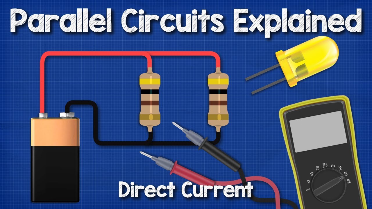
Image taken from the YouTube channel The Engineering Mindset , from the video titled DC parallel circuits explained - The basics how parallel circuits work working principle .
Electrical circuits are the unseen backbone of our modern world, powering everything from the smartphones in our pockets to the intricate systems that keep hospitals running. Understanding these circuits, even at a basic level, is no longer a luxury but a necessity for navigating daily life.
The Ubiquitous Nature of Electrical Circuits
Consider the simple act of turning on a light. Behind that flick of a switch lies a network of wires, resistors, and perhaps even capacitors, all working in harmony to illuminate your surroundings.
Think about your car, a marvel of engineering dependent on a complex web of electrical systems for ignition, lighting, and countless other functions.
Even seemingly simple appliances, like toasters and coffee makers, rely on sophisticated circuitry to deliver consistent performance.
The more we understand about these fundamental building blocks, the better equipped we are to interact with and appreciate the technology that shapes our lives.
Respecting the Power: Safety First
However, this ubiquitous presence also carries inherent risks. Electricity, while incredibly useful, can be dangerous if not handled with respect and understanding.
A misunderstanding of basic electrical principles can lead to shocks, burns, and even fires.
It is crucial to approach any interaction with electrical systems with caution and a commitment to safety.
This begins with a foundational knowledge of how circuits work, how components behave, and how to protect ourselves from harm. Always err on the side of caution. If you are unsure, consult a qualified electrician.
Parallel Circuits: A Fundamental Configuration
Among the various types of electrical circuits, the parallel circuit stands out as a particularly important and widely used configuration.
In a parallel circuit, components are arranged in such a way that the current has multiple paths to flow, rather than a single path as in a series circuit. This seemingly simple difference has profound implications for how the circuit behaves, especially concerning voltage.
Our Objective: Clarity on Voltage
This article aims to demystify the behavior of voltage within parallel circuits.
We will explore the fundamental principle that voltage remains constant across all components in a parallel circuit.
By providing a clear, concise, and accessible explanation, we hope to empower you with a deeper understanding of this essential concept, promoting both safety and a greater appreciation for the electrical world around us.
Electrical circuits are the unseen backbone of our modern world, powering everything from the smartphones in our pockets to the intricate systems that keep hospitals running. Understanding these circuits, even at a basic level, is no longer a luxury but a necessity for navigating daily life.
Among the many types of electrical circuits, the parallel circuit stands out for its unique properties and widespread applications. Before we can delve into the specifics of voltage behavior, it's crucial to first establish a solid understanding of what exactly constitutes a parallel circuit and how its components are arranged.
What Are Parallel Circuits? A Beginner's Guide
At its core, a parallel circuit is defined by the presence of multiple pathways for electrical current to traverse from the source to the load.
Unlike a series circuit, where components are arranged sequentially along a single path, a parallel circuit provides alternative routes for current flow.
This fundamental difference in configuration leads to distinct electrical characteristics, particularly concerning voltage and current distribution.
Defining Parallel Connections
In a parallel circuit, components such as resistors, batteries, or light bulbs are connected in such a way that their terminals are directly linked to each other.
Specifically, all positive terminals are connected to one common point, and all negative terminals are connected to another common point.
This creates multiple independent branches, each offering a separate route for current to travel from the voltage source back to the source.
Visualizing Parallel Circuits
The best way to understand parallel circuits is by looking at their schematic diagrams.
These diagrams use standard symbols to represent various components and their connections.
In a parallel circuit diagram, you'll observe that components are drawn side-by-side, with lines representing the wires connecting their terminals to the common points.
These diagrams clearly illustrate the multiple parallel pathways available for current flow, distinguishing them from the single path found in series circuits. Visualizing these diagrams can make understanding circuit behavior much easier.
Voltage: The Constant Companion in Parallel Circuits
Having established the structural nature of parallel circuits—multiple pathways diverging from a single source—we can now explore one of their defining characteristics: voltage behavior.
In a parallel circuit, the voltage across each component is identical to the voltage of the source. This is a fundamental rule and the cornerstone of understanding parallel circuit behavior.
It’s not merely a coincidence; it’s an inherent property dictated by the circuit's unique configuration.
Understanding Voltage Consistency
The consistency of voltage stems from the fact that each branch in a parallel circuit connects directly to the voltage source.
Imagine a system of parallel pipes connected to a water reservoir.
The water pressure (analogous to voltage) at the entrance of each pipe will be the same, regardless of the pipe's diameter or length (analogous to resistance).
Each pipe receives the full force of the reservoir's pressure.
Similarly, in a parallel electrical circuit, each branch experiences the full potential difference supplied by the voltage source.
This potential difference drives the flow of current through each branch, and because the potential difference is equal across all branches, the voltage is constant.
Measuring Voltage in Parallel Circuits
Measuring voltage in a parallel circuit is a straightforward process using a multimeter, a standard tool for electrical diagnostics.
To accurately measure voltage, you'll need a multimeter and a basic understanding of its operation.
Step-by-Step Guide:
-
Safety First: Always disconnect power from the circuit before making any measurements. This is a crucial safety precaution.
-
Setting Up the Multimeter: Select the "DC Voltage" (VDC) setting on your multimeter. Choose a voltage range slightly higher than the expected voltage of the circuit.
-
Connecting the Multimeter: Place the multimeter probes in parallel with the component you want to measure. This means connecting the red probe to the positive side of the component and the black probe to the negative side.
-
Reading the Measurement: Once connected, the multimeter will display the voltage across that component. Repeat this process for each component in the parallel circuit.
Interpreting Results:
The key observation will be that the voltage readings across each component should be approximately the same and equal to the source voltage.
Any significant deviation from this indicates a potential issue within that specific branch or the voltage source itself. Slight variations can occur due to component tolerances or minor voltage drops in connecting wires.
Deciphering the Voltage and Current Relationship with Ohm's Law
With a firm grasp on the consistent voltage across parallel circuit branches, attention now turns to current.
It's equally important to understand how voltage and current interact within these circuits.
Ohm's Law provides the key to unlocking this relationship.
Unveiling Ohm's Law in Parallel Circuits
Ohm's Law, expressed as V = IR, states that voltage (V) is equal to current (I) multiplied by resistance (R).
This fundamental law governs the behavior of electrical circuits.
Applying Ohm's Law to parallel circuits reveals how current behaves in each branch.
Since voltage is constant, the current through each branch is inversely proportional to its resistance.
A branch with lower resistance will draw more current, while a branch with higher resistance will draw less.
Current Division: The Impact of Resistance
In a parallel circuit, the total current from the source divides among the different branches.
The amount of current that flows through each branch is dictated by the resistance of that branch.
Imagine a river splitting into multiple streams.
The wider streams (lower resistance) will carry more water (current), while the narrower streams (higher resistance) will carry less.
This principle, known as current division, is crucial for understanding parallel circuit behavior.
Calculating Total Current in a Parallel Circuit
To determine the total current flowing from the source, a straightforward method is to calculate current in each branch and sum them.
First, use Ohm's Law to calculate the current in each individual branch: I = V/R.
Divide the constant voltage by the resistance of each branch.
Then, add the current values of all branches to find the total current (Itotal).
Itotal = I1 + I2 + I3 + ... In, where n is the number of branches.
This sum represents the total current drawn from the voltage source.
Understanding how to calculate total current is essential for circuit design and troubleshooting.
Kirchhoff's Voltage Law: Reinforcing the Constant Voltage Principle
Having explored Ohm's Law and its implications for current division in parallel circuits, a natural question arises: how can we further solidify our understanding of voltage behavior in these configurations? The answer lies in Kirchhoff's Voltage Law (KVL), a fundamental principle that provides an independent confirmation of the constant voltage characteristic of parallel circuits.
Understanding Kirchhoff's Voltage Law (KVL)
KVL, at its core, states that the algebraic sum of all voltages around any closed loop in a circuit must equal zero. In simpler terms, if you start at a point in a circuit and trace a path back to the same point, accounting for all voltage gains (e.g., from a voltage source) and voltage drops (e.g., across a resistor), the total change in voltage will be zero.
This law is a direct consequence of the principle of conservation of energy. The energy gained from the voltage source must be entirely consumed by the components within the loop.
Applying KVL to Parallel Circuits
In a parallel circuit, each branch forms a separate closed loop with the voltage source. Let's consider a simple parallel circuit with a voltage source (V) and two resistors (R1 and R2) connected in parallel.
Loop 1: Starting at the negative terminal of the voltage source and traversing through resistor R1 back to the positive terminal, the loop equation is: V - VR1 = 0, where VR1 is the voltage drop across resistor R1. Therefore, V = VR1.
Loop 2: Similarly, tracing the loop through resistor R2 gives: V - VR2 = 0, meaning V = VR2.
These equations derived from KVL clearly demonstrate that the voltage drop across each resistor (VR1 and VR2) is equal to the source voltage (V).
This confirms our earlier understanding that voltage is constant across all components in a parallel circuit.
KVL as Confirmation of Constant Voltage
KVL doesn't just state that voltage is constant. It provides a rigorous, mathematical framework to prove it. By applying KVL to each loop within a parallel circuit, we derive equations that explicitly show the voltage across each component is identical to the source voltage.
This is particularly important when analyzing more complex parallel circuits with multiple branches.
Even with varying resistor values and current distributions, KVL remains valid, consistently reinforcing the fundamental principle of constant voltage.
Practical Implications
The verification offered by KVL has significant practical implications:
-
Circuit Design: Engineers can confidently design parallel circuits, knowing that each component will receive the intended voltage.
-
Troubleshooting: KVL aids in identifying faults. If voltage measurements deviate from KVL predictions, it indicates a problem within the circuit.
-
Circuit Analysis: KVL provides a robust method for analyzing complex parallel circuits and helps to better understand the voltage at different points in the circuit.
In conclusion, Kirchhoff's Voltage Law is not merely a theoretical concept.
It serves as a powerful tool for understanding, confirming, and applying the principle of constant voltage in parallel circuits, which is fundamental to electrical engineering.
Kirchhoff's Voltage Law provides a valuable theoretical framework for understanding parallel circuits, but its true significance becomes even clearer when we examine how these circuits function in the world around us. From powering our electronic devices to safely distributing electricity in our homes, parallel circuits are indispensable components of modern technology.
Parallel Circuits in Action: Real-World Examples
Parallel circuits aren't just theoretical concepts; they are integral to numerous everyday applications. Understanding how these circuits operate in practice provides valuable insights into their functionality and reinforces the importance of the principles we've discussed. Let's examine a few prominent examples.
Connecting Batteries in Parallel: Boosting Capacity
One common application of parallel circuits is in connecting batteries to increase current capacity.
Unlike series connections, which increase voltage, connecting batteries in parallel maintains the voltage while increasing the available current.
This is crucial in applications where a device requires a sustained high current draw, such as in electric vehicles or high-powered audio amplifiers.
Consider a scenario where a device requires 12V but needs to operate for an extended period. Connecting two 12V batteries in parallel effectively doubles the available current, allowing the device to run for twice as long before the batteries are depleted.
This configuration ensures a stable voltage supply while meeting the current demands of the load.
Household Wiring: A Parallel Network for Power Distribution
Perhaps the most ubiquitous example of parallel circuits in action is in household wiring.
Electrical outlets and appliances in a home are wired in parallel to the main power supply.
This parallel configuration ensures that each appliance receives the same standard voltage (e.g., 120V in North America), regardless of whether other appliances are switched on or off.
Imagine a scenario where household circuits were wired in series.
If you turned on a lamp, the voltage available to other appliances further down the line would decrease, leading to dimming lights and potentially malfunctioning devices.
The parallel arrangement prevents this issue.
Each outlet provides a direct connection to the main power source, ensuring a consistent voltage supply.
This allows you to use multiple appliances simultaneously without affecting the performance of others.
Implications of Parallel Wiring in Homes
The parallel nature of household wiring also has important implications for circuit protection.
Each branch of the circuit is typically protected by a fuse or circuit breaker.
If a fault occurs in one branch, such as a short circuit, the fuse or circuit breaker for that branch will trip, isolating the fault and preventing it from affecting other parts of the house.
This safety feature is crucial for preventing electrical fires and protecting appliances from damage.
Understanding Load and Parallel Circuits
It's also important to understand how adding more devices to a parallel circuit affects the overall load on the circuit.
Each additional device connected in parallel draws current from the power source.
As more devices are added, the total current flowing through the circuit increases.
If the total current exceeds the capacity of the circuit wiring or the rating of the circuit breaker, it can lead to overheating and potentially cause a fire.
This is why it's crucial to avoid overloading circuits by plugging too many high-power devices into the same outlet or circuit.
By understanding these real-world examples, we can appreciate the fundamental role of parallel circuits in our daily lives and the importance of adhering to safety guidelines when working with electrical systems.
Parallel circuits are integral to our daily lives, silently powering our homes and devices. Yet, their widespread use often overshadows the inherent risks they pose if not handled with care. Before delving into practical applications and theoretical intricacies, it’s paramount to address a crucial aspect: safety. Understanding and mitigating the dangers associated with parallel circuits isn't merely good practice, it's an absolute necessity for preventing electrical hazards and ensuring personal well-being.
Safety First: Avoiding the Dangers of Parallel Circuits
Working with electricity, even in seemingly simple parallel circuits, demands respect and a comprehensive understanding of potential hazards. Unlike theoretical exercises, real-world circuits can deliver dangerous shocks and trigger fires if mishandled. Therefore, a robust safety-first approach is non-negotiable.
Overloading: The Silent Threat
One of the most significant dangers in parallel circuits is overloading. In a parallel configuration, each component provides a separate path for current. As more devices are added, the total current drawn from the source increases.
This can quickly exceed the circuit's capacity, leading to overheating of wires and components.
Overheating can melt insulation, creating short circuits and igniting surrounding materials.
This is especially true in household wiring, where multiple appliances connected to the same circuit can easily overload the system.
Recognizing the Signs of Overload
Being able to spot warning signs of circuit overload is a critical skill. These signs include:
- Dimming lights when appliances are turned on.
- Warm or discolored outlets.
- Frequently tripping circuit breakers or blown fuses.
- A burning smell emanating from outlets or appliances.
If you observe any of these symptoms, it’s crucial to immediately reduce the load on the circuit and investigate the underlying cause. Ignoring these signs can have disastrous consequences.
The Crucial Role of Fuses and Circuit Breakers
Fuses and circuit breakers are indispensable safety devices designed to protect electrical circuits from overcurrent conditions. They act as safety valves, interrupting the flow of electricity when the current exceeds a predetermined level.
Fuses contain a thin wire that melts and breaks the circuit when subjected to excessive current.
Circuit breakers, on the other hand, use a mechanical switch that trips and opens the circuit.
Both devices prevent overheating and potential fires by quickly cutting off the power supply.
Selecting the Right Protection
It's vital to use fuses or circuit breakers with the correct amperage rating for the specific circuit. Using a fuse with a higher rating than the circuit is designed for defeats its purpose. It allows excessive current to flow unchecked, negating the safety benefits.
Likewise, replacing a blown fuse or tripped breaker with one of a higher rating is extremely dangerous. Consult a qualified electrician to ensure the appropriate protection is in place for all circuits.
Disconnect Power: The Golden Rule
Before undertaking any work on electrical circuits, whether troubleshooting, modifying, or simply inspecting, the first and most important step is to disconnect the power.
This means turning off the circuit breaker or removing the fuse that supplies power to the circuit you'll be working on.
Never assume a circuit is de-energized without verifying it using a reliable voltage tester.
Even after disconnecting the power, treat all wires and components as if they are live until proven otherwise.
Lockout/Tagout Procedures
In industrial or commercial settings, lockout/tagout procedures should be strictly followed to prevent accidental re-energization of circuits during maintenance or repair.
These procedures involve physically locking the circuit breaker in the off position and attaching a tag indicating that the circuit is being worked on.
This ensures that no one can inadvertently restore power while someone is working on the circuit, preventing potentially fatal accidents.
By understanding the potential dangers of parallel circuits and consistently adhering to safety protocols, you can significantly reduce the risk of electrical hazards. Always prioritize safety, and when in doubt, consult a qualified electrician. Electricity is a powerful tool, but like any tool, it requires respect and careful handling.
Parallel circuits are integral to our daily lives, silently powering our homes and devices. Yet, their widespread use often overshadows the inherent risks they pose if not handled with care. Before delving into practical applications and theoretical intricacies, it’s paramount to address a crucial aspect: safety. Understanding and mitigating the dangers associated with parallel circuits isn't merely good practice, it's an absolute necessity for preventing electrical hazards and ensuring personal well-being.
That being said, even with the utmost care and adherence to safety protocols, parallel circuits can sometimes malfunction. Efficient troubleshooting is key to quickly restoring functionality and preventing further issues.
Troubleshooting Common Parallel Circuit Issues
Troubleshooting parallel circuits involves systematically identifying and resolving problems like open circuits, short circuits, or component failures. A solid understanding of parallel circuit behavior, coupled with the proper tools and techniques, is crucial for effective diagnostics.
The Indispensable Multimeter
The multimeter is an essential tool for troubleshooting any electrical circuit, and parallel circuits are no exception. It allows you to measure voltage, current, and resistance, providing valuable insights into the circuit's operation.
Identifying Open Circuits
An open circuit occurs when a break in the conductive path prevents current from flowing through a branch.
This could be due to a broken wire, a faulty switch, or a burned-out component.
Using a multimeter in voltage mode, you can identify an open circuit by measuring the voltage across the suspected break. A significant voltage reading across the open indicates that the circuit is indeed broken at that point.
Alternatively, in resistance mode and with the circuit de-energized, an open circuit will show infinite resistance.
Detecting Short Circuits
A short circuit is an unintended low-resistance path that allows current to bypass the intended circuit elements.
This often results in excessive current flow, potentially damaging components and posing a fire hazard.
In parallel circuits, short circuits can be particularly problematic, as the increased current draw can overload the entire circuit.
Using a multimeter in resistance mode and with the circuit de-energized, you can check for shorts by measuring the resistance between points that should not be directly connected.
A very low resistance reading indicates a short circuit.
In voltage mode, a short circuit will show close to zero voltage because current takes the path of least resistance.
Understanding Component Failure
Component failure, such as a resistor burning out or a capacitor failing, can significantly impact the behavior of a parallel circuit.
In a parallel circuit, the failure of one component doesn't necessarily stop the entire circuit from functioning, but it will alter the current distribution and overall resistance.
Impact on Current Flow
If a resistor in a parallel branch fails (opens), the current through that branch will drop to zero.
This will cause the total current drawn from the source to decrease, potentially affecting the performance of other components in the circuit.
Conversely, if a component shorts, the current through that branch will increase dramatically, potentially overloading the circuit.
Analyzing Voltage Readings
While voltage is ideally constant across all branches in a parallel circuit, component failure can subtly affect voltage readings.
For example, a partially failed component might exhibit a slightly lower voltage reading than other branches.
However, significant voltage drops are more indicative of wiring issues or connection problems rather than the failing component itself, especially under high current draw.
Close attention must be paid.
By carefully analyzing voltage, current, and resistance measurements with a multimeter, you can effectively diagnose and resolve common issues in parallel circuits, ensuring their safe and reliable operation.
Video: Voltage in Parallel: Simple Guide That Will Save Your Life

FAQs: Voltage in Parallel Explained
Here are some frequently asked questions about voltage in parallel circuits, designed to clarify key concepts and help you apply this knowledge effectively.
Does the voltage stay the same across all components in a parallel circuit?
Yes, that's the defining characteristic of a parallel circuit. The voltage in parallel remains constant across each branch. This is because all components are connected to the same two points.
What happens if batteries with different voltages are connected in parallel?
Connecting batteries with differing voltages in parallel is generally not recommended. The higher voltage battery will attempt to charge the lower voltage battery, leading to potentially damaging and even dangerous conditions. It's best to use batteries of the same voltage.
If voltage in parallel remains constant, how does the current behave?
While voltage remains the same, the current divides across each branch in a parallel circuit. The total current entering the parallel section is equal to the sum of the currents in each individual branch, following Kirchhoff's Current Law.
Why is understanding voltage in parallel important?
Understanding voltage in parallel is crucial for safely and effectively designing electrical circuits. From wiring household appliances to more complex electronic systems, knowing that the voltage remains constant allows you to correctly calculate current and power requirements for each component.